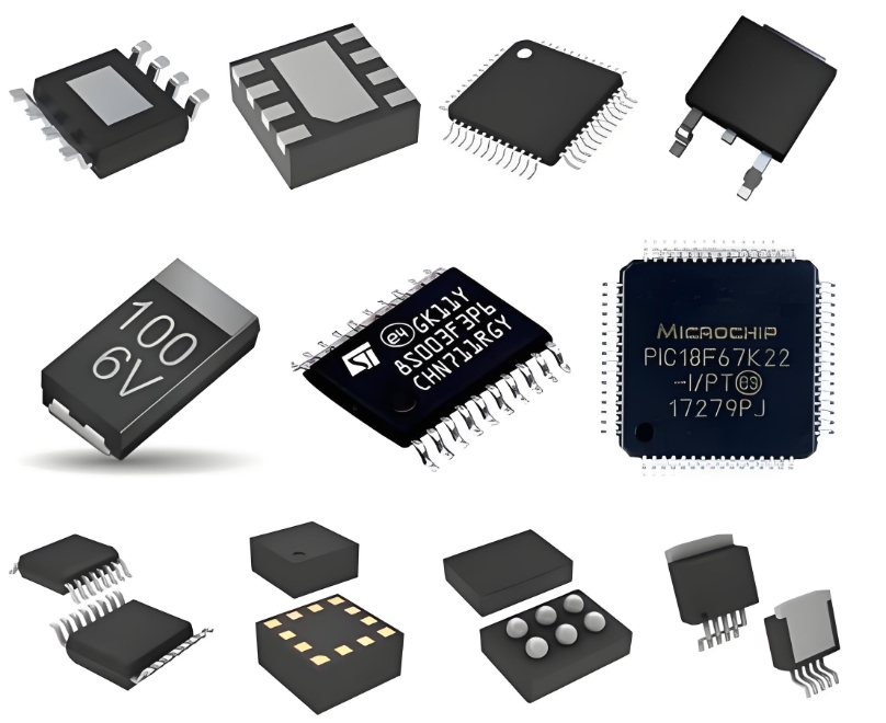
**Unveiling the AD9243AS: A Comprehensive Analysis of its Architecture and System-Level Integration**
The relentless pursuit of higher fidelity in signal digitization has cemented the role of high-performance analog-to-digital converters (ADCs) as the critical bridge between the analog and digital worlds. Among these components, the **AD9243AS from Analog Devices stands as a quintessential example of a high-dynamic-range, dual-channel ADC**, engineered for demanding applications in communications, medical imaging, and instrumentation. This article delves into the architectural nuances and system-level integration strategies that define this powerful component.
**Architectural Prowess: A Dual-Channel Pipeline**
At its core, the AD9243AS is built upon a sophisticated **pipelined architecture**, a design choice that optimally balances conversion speed, resolution, and power consumption. Each of its two identical channels features a 14-bit resolution sampling at speeds up to 65 MSPS (Mega Samples Per Second). The pipeline is segmented into multiple stages, each containing a sample-and-hold (S/H) amplifier, a low-resolution sub-ADC (e.g., a flash converter), and a digital-to-analog converter (DAC) for residue generation. This structure allows subsequent stages to process the residue from the previous one, enabling high-speed operation without the exponential complexity of a full-flash architecture.
A critical innovation within its architecture is the integrated **high-performance sample-and-hold amplifier and voltage reference**. The on-chip SHA minimizes aperture jitter and ensures accurate sampling of high-frequency inputs. Furthermore, the precision internal reference circuitry eliminates the need for external reference components, simplifying board design and enhancing overall stability against temperature and supply voltage variations. This integration is paramount for achieving the converter's exceptional **spurious-free dynamic range (SFDR) and signal-to-noise ratio (SNR)**.
**Digital Output and Clocking: Ensuring Data Integrity**
The digital output interface is a crucial part of the ADC's architecture. The AD9243AS provides demultiplexed digital outputs, meaning the data from each channel is presented on separate output buses. This feature eases the interface with FPGAs or ASICs, as it reduces the data rate each receiving device must handle. The outputs are typically LVDS (Low-Voltage Differential Signaling) or CMOS, chosen for their low noise and robust immunity to common-mode interference, which is vital for maintaining data integrity in noisy system environments.
Clock management is another cornerstone of its performance. The device requires a low-jitter clock source, as **clock jitter is a primary limiting factor for SNR at high input frequencies**. The AD9243AS's design is optimized to minimize its internal jitter contribution, but system designers must provide a clean, stable external clock to unlock the converter's full potential. The inclusion of a clock duty cycle stabilizer can also be a key feature, ensuring consistent performance regardless of variations in the clock input's duty cycle.
**System-Level Integration: Challenges and Best Practices**
Integrating a high-speed ADC like the AD9243AS into a larger electronic system presents several challenges that must be meticulously addressed to achieve datasheet performance.

1. **Power Supply and Decoupling:** High-speed ADCs are notoriously sensitive to power supply noise. Implementing a robust power delivery network with multiple layers of decoupling is non-negotiable. This involves using a combination of bulk capacitors, ceramic capacitors, and ferrite beads to filter noise at different frequencies. **Separate analog and digital supply planes** are essential to prevent digital switching noise from corrupting the sensitive analog sections.
2. **PCB Layout and Grounding:** A continuous ground plane is highly recommended to provide a low-inductance return path for signals. The layout must separate analog and digital sections, routing high-speed digital output lines away from the analog input and clock traces to prevent crosstalk. The placement of decoupling capacitors must be as close as possible to the supply pins to minimize parasitic inductance.
3. **Input Signal Conditioning:** The analog input interface typically requires a driver amplifier and an anti-aliasing filter (AAF). The driver must have sufficient slew rate, bandwidth, and low distortion to preserve the input signal's integrity. The AAF, usually a passive RC or active filter, is critical for band-limiting the input signal to prevent higher-frequency noise from aliasing back into the Nyquist zone, thereby degrading SNR.
4. **Digital Data Capture:** Successfully capturing the high-speed digital output data stream demands careful timing analysis. The receiving device (FPGA) must be configured to properly latch the data using the provided data clock (DCO). Techniques like double-data-rate (DDR) capturing and careful adjustment of latch timing within the FPGA are standard practice to avoid metastability and ensure error-free data transfer.
**ICGOODFIND**
The AD9243AS exemplifies the intricate balance between analog precision and digital throughput. Its success in a system hinges not just on its impressive standalone specifications—such as its high SFDR and integrated design—but on a holistic approach to integration. **Mastering the intricacies of power integrity, signal routing, and clock management is the true key to leveraging the full capabilities of this high-performance ADC**, transforming it from a mere component into the heart of a high-fidelity data acquisition system.
**Keywords:**
1. **Pipeline Architecture**
2. **Spurious-Free Dynamic Range (SFDR)**
3. **System-Level Integration**
4. **Clock Jitter**
5. **Signal Conditioning**
